A technical overview of the photonic, optical, and control system technologies that underpin our marking and measurement platforms. Understanding these fundamentals enables informed system selection and process optimization.
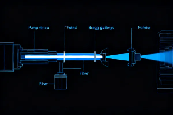
Our marking systems employ rare-earth-doped fiber lasers where the gain medium is an ytterbium-doped silica fiber core, typically 6–10 microns in diameter. Pump diodes at 915nm or 976nm excite the ytterbium ions, which emit at 1064nm through stimulated emission. Fiber Bragg gratings etched into the fiber cladding form the resonant cavity.
This architecture delivers several measurable advantages over traditional Nd:YAG rod lasers: wall-plug efficiency exceeds 30% (versus 3–5% for lamp-pumped YAG), beam quality M² remains below 1.3 across the full power range, and the fiber geometry provides inherent thermal management through the high surface-area-to-volume ratio of the active medium.
Our UV laser systems use third-harmonic generation (THG) to convert the 1064nm fundamental wavelength through two nonlinear optical crystals (LBO and BBO) to produce 355nm ultraviolet output. At this wavelength, photon energy reaches 3.49eV, which exceeds the bond dissociation energy of most organic polymers (C-C bonds: 3.6eV, C-H bonds: 4.3eV).
This enables a fundamentally different material removal mechanism: photochemical bond breaking rather than thermal vaporization. The practical result is a heat-affected zone (HAZ) typically under 5 microns, compared to 50–200 microns for infrared processing. This distinction is critical for marking on thin polyimide flex circuits (25–50μm thickness), glass substrates where thermal shock causes fracture, and medical-grade polymers where carbonization compromises biocompatibility.
Technical limitation: THG conversion efficiency is approximately 15–20%, limiting practical UV output power to 15W for most industrial configurations. Applications requiring higher throughput on UV-compatible substrates may benefit from our hybrid fiber-UV configurations.
The galvanometer scanning head is the precision positioning subsystem that directs the focused laser beam across the marking field. Two servo-driven mirrors mounted on low-inertia galvo motors deflect the beam in X and Y axes independently. Our systems use Scanlab and Raylase scanning heads with digital position feedback achieving positioning repeatability below ±3 microns.
The f-theta telecentric lens assembly below the scanning mirrors ensures that the focused spot maintains constant size and perpendicular incidence across the entire marking field. This is not trivial: without telecentric correction, a beam deflected to the field edge would produce an elliptical spot approximately 1.4x larger than the on-axis spot, causing visible mark quality degradation at field boundaries.
| Parameter | Specification |
|---|---|
| Marking speed | Up to 12,000 mm/s |
| Positioning repeatability | ±0.003mm |
| Standard field sizes | 110×110mm, 175×175mm, 300×300mm |
| Minimum spot diameter | 20μm (110mm field), 35μm (175mm field) |
| Step response time | <0.3ms for 1° deflection |
Our VX-Series platforms integrate a coaxial machine vision camera within the marking head assembly, enabling in-situ code verification without part transfer or secondary inspection stations. The camera captures the marked code immediately after laser processing, and our proprietary grading algorithm evaluates it against ISO/IEC 15415 (2D codes) or ISO/IEC 15416 (1D barcodes) standards.
The verification process measures seven parameters for each DataMatrix code: symbol contrast, modulation, fixed pattern damage, axial non-uniformity, grid non-uniformity, unused error correction, and print growth. Each parameter receives an individual grade (A through F), and the overall code grade equals the lowest individual parameter grade. Our systems achieve 99.97% first-pass Grade A results across standard automotive and medical marking applications.
Important caveat: In-situ verification provides process monitoring, not final inspection. For regulatory submissions requiring independent verification (e.g., FDA UDI or automotive PPAP), we recommend offline verification with a calibrated external reader as the documented record of compliance.
Maintaining the laser beam at its focal plane is essential for consistent mark quality. A defocus of just 0.5mm on a 110mm field lens produces a 40% increase in spot diameter, resulting in measurably reduced contrast and line definition. Our autofocus subsystem uses a laser triangulation sensor to measure the workpiece surface distance at up to 4,000 Hz and drives a motorized Z-axis stage to maintain focal position within ±0.05mm.
For non-planar surfaces, our 3D marking capability uses a variable beam expander (VBE) within the optical path. By continuously adjusting the divergence of the beam entering the galvo head, the effective focal length shifts dynamically, allowing the system to mark on curved, stepped, or inclined surfaces with up to ±30mm of Z-range compensation at marking speeds above 1,000mm/s.
All Keyence marking platforms use a Beckhoff EtherCAT-based control architecture that synchronizes the laser source, galvo positioning, autofocus drive, and vision verification within a single deterministic communication bus. The EtherCAT cycle time of 250 microseconds ensures that laser pulse triggering is synchronized with mirror position to within ±1 microsecond, eliminating the pulse placement errors that degrade mark quality at high speeds.
For production line integration, our controller exposes standard industrial interfaces: EtherNet/IP, PROFINET, and CC-Link IE Field Basic for PLC communication; RS-232C and TCP/IP for host system data exchange; and discrete I/O for trigger, busy, and error signaling. Job data (marking content, position offsets, parameter selection) can be loaded dynamically from the host MES or ERP system via our documented API.
Our applications engineering team maintains a validated parameter database covering 340+ material-substrate combinations. Below is a representative selection demonstrating the range of substrates our systems address.
Black annealing mark for medical UDI applications. Optimized to preserve passive oxide layer and pass ASTM F2129 corrosion testing.
High-contrast DataMatrix on as-cast surface. Parameters validated for readability after e-coat, powder coat, and shot blast processes.
Controlled-depth marking for aerospace turbine components. Depth held within ±5μm to minimize fatigue life impact per AMS 2431.
UV photochemical marking on 25μm Kapton film. No charring, delamination, or substrate warpage at production speeds.
Black oxide marking for orthopedic implants. Biocompatibility maintained per ISO 10993, verified through independent cytotoxicity testing.
UV micro-marking for board-level traceability. 1mm x 1mm DataMatrix codes readable at SMT line speeds with automated verification.
Request a technical deep-dive with our applications engineering team. We can provide detailed parameter data, process capability studies, and sample marking results for your specific material and application requirements.